|
|
|||||||||||||||||||||||
|
SmartDO eNews Feb. 26, 2013
: Using SmartDO and ANSYS Workbench/CFD for Design Optimization
Introduction The SmartLink module of SmartDO can linked with any exposed parameters in ANSYS Workbench, and perform design optimization directly without parametric experiment and/or statistical study. With the powerful Direct Search optimizer in SmartDO, the user can virtually optimize on any physics/disciplines by using ANSYS as an simulation black box. In this issue of SmartDO eNews, we will introduce how to use SmartLink to perform design optimization with ANSYS Workbench CFD. We will use a simple 3D flowpath to demonstrate the convenient and efficient new interface of SmartDO. Although the model is constructed in Fluent, the same process can principle can be also applied on CFX. Description of the Problem Consider a 3D flowpath shown in Figure 1. The fluid flows in a pipe with a bigger diameter, and flows out through a smaller diameter. The transition section in the middle is to be optimize, so that the power loss is as small as possible. Due to some design consideration, the length of the transition section should be less then certain value. The optimization problem is formulated as Find : {H1, R1, H2} To Minimize : Power Loss Subjected to : H1+H2 < 3 Inlet Pressure < 1 Pa In the flowing section, we will show who to solve this problem through SmartDO and ANSYS Workbench CFD. 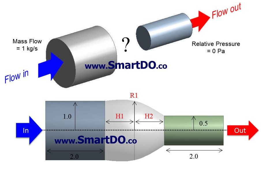
Figure 1 Schema of The 3D Flowpath Step 1 : Build Parametric Geometry Model in DesignModeler The first step is to build the geometry model in DesignModeler, as shown in Figure 2. After the geometry is created, simply click on the blank box of the parameters, and a "D" will be marked in it, as shown in Figure Figure 3. Anything (input variables) marked with "D" here in Workbench can be linked as Design Variables in SmartDO. The detailed steps won't be elaborated here. Please refer to your ANSYS manual or tutorials for details. 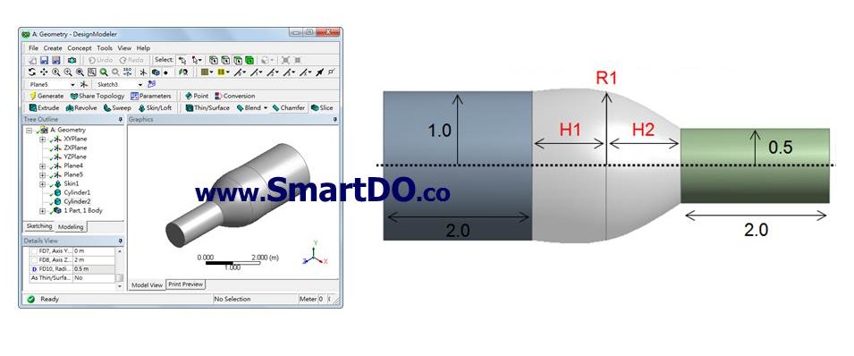
Figure 2 Build The Geometry Model in DesignModeler 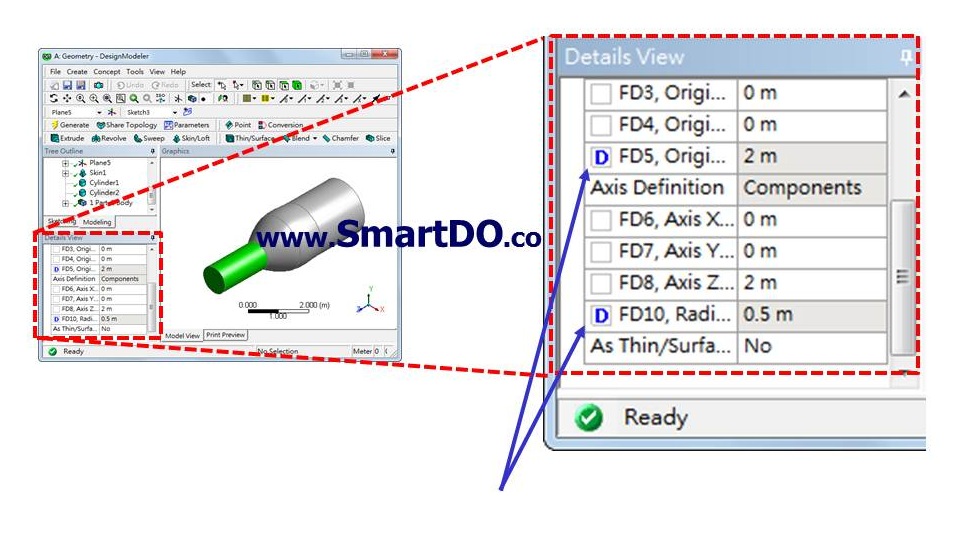
Figure 3 Anything Marked with "D" Here Can Be Linked As Design Variables in SmartDO Step 2 : Setting Up BC, Solution, and Retrieve Result From CFD-Post 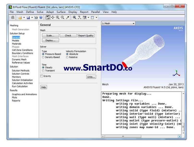
Figure 4 Set Up BC and Solution in ANSYS CFD 
Figure 5 Anything Calculated as Output Parameter Can Be Linked As Objective Function and Constraints in SmartDO Step 3 : Check List of Parameters in Workbench All the input/output created above can be checked and listed in Workbench, as shown in Figure 6. In the next step, we will import this parameter table into SmartDO and perform modeling of design optimization. 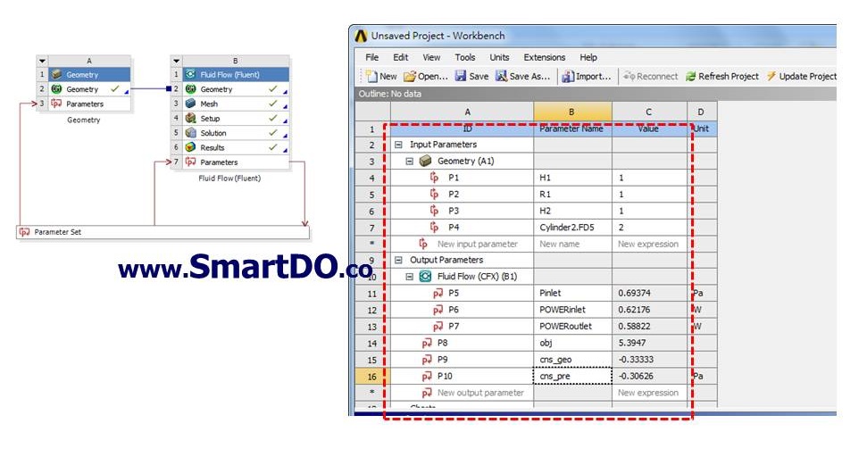
Figure 6 Parameter Table in Workbench
Step 4 : Open SmartDO and Set Up Controlling Parameters Open SmartDO and you will see its interface as shown in Figure 7. Go to (Main Menu > SmartLink > ANSYS Workbench > Optimizer Control) and set up the optimization parameters (number of design variables and constraints) as shown in Figure 8. Note that the default solver usually works quite well, and you won't have to worry about tweaking with the optimizer at all. 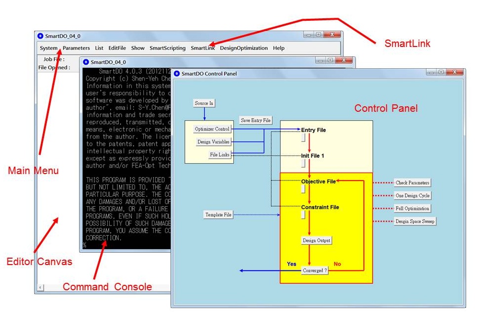
Figure 7 SmartDO Interface 
Figure 8 Setting Up Controlling Parameters in SmartDO Step 5 : Link Workbench File and Import Its Parameters Pick the Workbench file you want to link through (Main Menu > SmartLink > ANSYS Workbench > Link Workbench Model), as shown in Figure 9. and set up the optimization parameters (number of design variables and constraints) as shown in Figure 9. Click on the [Update Project] button to update the Workbench project. Then Click on the [Import Parameters] button to import the parameter table of Workbench project, as shown in Figure 10. 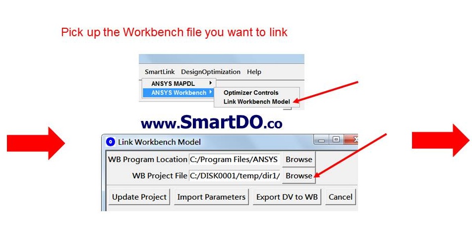
Figure 9 Pick Workbench Project to Link With SmartDO
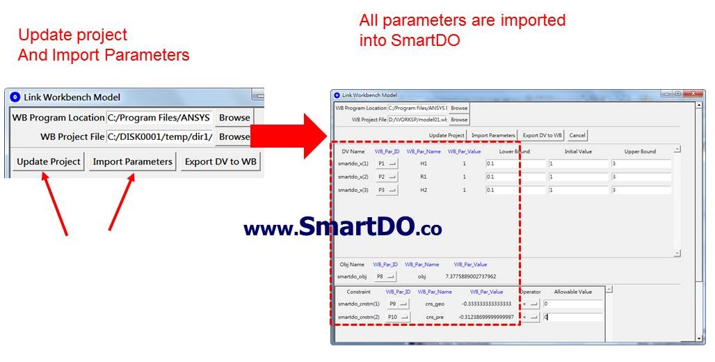
Figure 10 Update the Project and Import Parameters From Workbench Step 6 : Link DVs, Objective Function and Constraint in SmartDO with Workbench Parameters After the parameters in Workbench is imported, you can use the pull-down men in the DV list to linked with the Input Parameters in Workbench (Figure 11), and type in the Lower Bound, Upper Bound and Initial Value for design optimization (Figure 12). Also use the pull-down menu to link the objective function and constraints in SmartDO with Workbench Output Parameters, and define the limitation of the constraints in Figure 13. Now you are done with the modeling of design optimization. All necessary linkage between SmartDO and Workbench are established, as shown in Figure 14. 
Figure 11 Link SmartDO DVs with Workbench Input Parameters

Figure 12 Define Lower Bound, Upper Bound and Initial Value for
Design Optimization in SmartDO
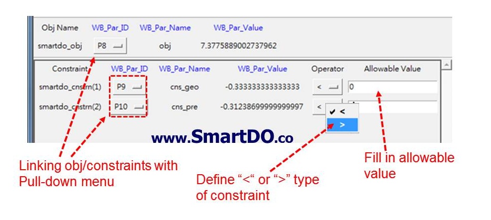
Figure 13 Link the Objective Function and Constraints in SmartDO,
and Define the Limitation of the Constraints
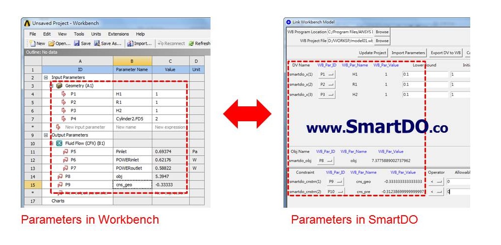
Figure 14 All Necessary Linkage Between SmartDO
and Workbench Established Now you can pull down the sliding bar to the button of the dialog box, and click on [Write SmartDO Model] as shown in Figure 15. Go back to the Control Panel and you will see the model is ready to run as shown in Figure 16. Click on the [Full Optimization] model and the optimization will begin. Since SmartDO uses the Direct Global Search technology, you don't have to perform statistically parametric study. After few automatic design iterations, SmartDO will get the optimum design for you automatically. For our problem here, the Initial Design and Optimum Design are shown in Figure 17 and 18. For this model, we can reduce the power loss by 74 % (optimal relative to initial design). 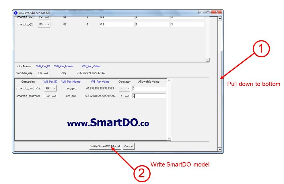
Figure 15 Write SmartDO Model
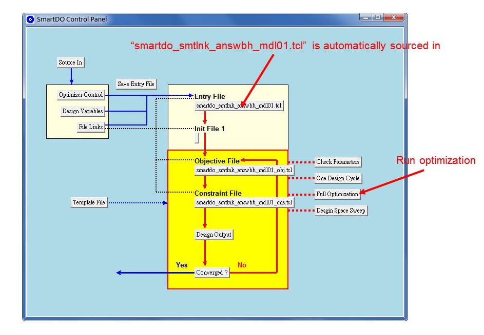
Figure 16 Run Optimization in SmartDO 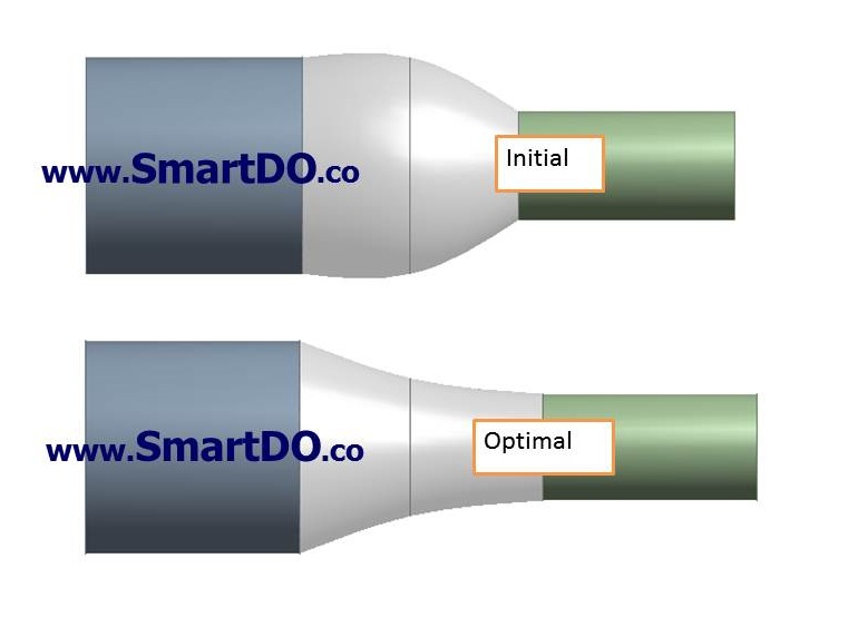
Figure 17 Initial (Top) vs Optimal (Bottom) Design by SmartDO 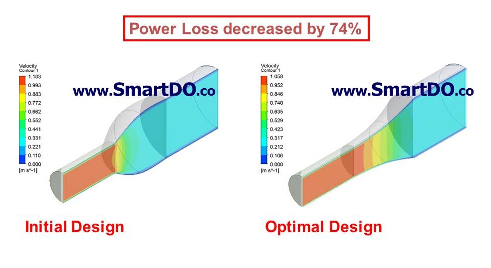
Figure 18 Initial (Left) vs Optimal (Right) Design by SmartDO Conclusion and Remarks In this issue of the SmartDO eNews, we show you how the SmartLink interface in SmartDO can easily link with the parameters in ANSYS Workbench for CFD Optimization. With the powerful and stable solver in SmartDO, design optimization can be easily performed. For details about SmartDO, please visit our web site at http://www.SmatDO.co All brand or product names are trademarks or registered trademarks of their respective holders. Copyright of all materials in the links belongs to their respective authors. I am not responsible for any contents inside any links. (c)Copyright, 2005-, FEA-Opt Technology. All rights reserved.
|
|
|||||||||||||||||||||||
| Copyright © FEA-Opt Technology Design by Iron Spider | ||||||||||||||||||||||||
|
|
||||||||||||||||||||||||